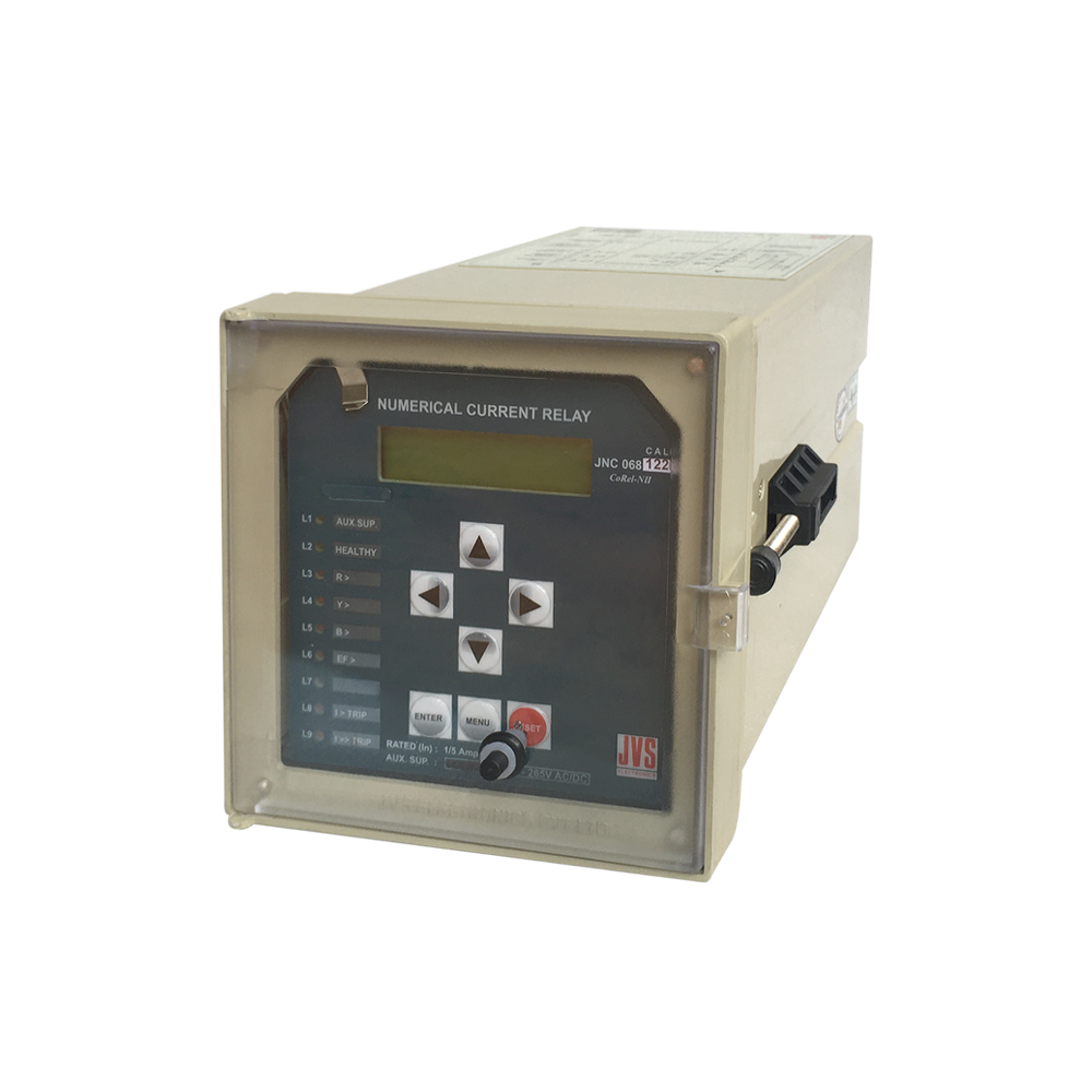
INVERSE TIME NUMERICAL CURRENT RELAY WITHOUT COMMUNICATION
₹35,750.00
Product Code: JNC 068CALPS
Time line :Products will be shipped within 3 weeks from the date of order
Stock In Stock
Viewed 5975 times
Categories
Cart
Account
Search
Recent View
All Categories
×
-
Products Category
- Earth Leakage Relays
- Electromechanical Auxiliary & High Speed Tripping Relays
- Electronic Hooters
- LED Indicating Lamps
- LED Semaphore Indicators
- Micro Processor Based Directional / Non-directional, Non-Communicable Current Relays
- MICRO PROCESSOR BASED INSTANTANEOUS / DEFINITE TIME AC VOLTAGE RELAYS
- Micro Processor Based Multi Shot, Auto Reclose Relays
- Micro Processor Based Neutral Earth Resistor Monitoring Relays
- Micro Processor Based PT Fuse Failure Relays
- MICRO PROCESSOR BASED RESTRICTED E/F RELAYS
- Micro Processor Based Trip Circuit Supervision Relays
- Numerical Check Synchronizing Relays
- Numerical Directional / Non-directional, Non-Communicable Current Relays
- Numerical Non-directional Inverse Time Current Relays Without Communication
- NUMERICAL OVERFLUX RELAYS
- Numerical Transformer Differential Relays
- Panel Accessories
- Push Buttons
- Semaphore Indicators
- Terminal Blocks & Plugs for Testing
- Time Delay Relays
- Two Stage Frequency Relays
- Micro Processor Based Inverse Time Non- Directional, Non-communicable Current Relays
- Non-directional Inverse Time Current Relays With/without Communication
- Micro Processor Based Inverse Time Non-directional, Non-communicable Current Relays
- Micro Processor Based Instantaneous / Definite Time Ac Voltage Relays
- Micro Processor Based Instantaneous / Definite Time Battery E/F Relays
- Micro Processor Based Instantaneous / Definite Time Current Relays
- Micro Processor Based Instantaneous / Definite Time Dc Voltage Relays
Shopping Cart
×
Your shopping cart is empty!
Search
×
Recent View Products
×
Product Description
Features
- Programmable CT secondary current for 1A / 5A rating
- Programmable system rated frequency (50/60Hz)
- Display of Primary current
- Available in many variants to suite main and back-up over-current protection schemes
- Available in both Low load and normal load configurations
- Choice of 6 IDMT curves and definite time with hi-set (two stage characteristics)
- Cold load pick-up
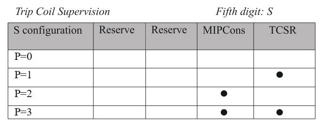
- MIPConS for preventing E/F element operation during single-phasing
- Trip Coil Supervision Relay
- Multi-short auto re-closer facility
- Self supervision facility
- Trip test facility
- History of 200 latest comprehensive fault records along with settings
- Latest 100 event records can be stored
Application
The relay provides time graded phase and earth fault (2 stage) protection, (high impedance) restricted earth fault protection. Certain advanced features such as “Cold load pickup” and MIPConS improves the sensitivity, stability and availability of the system.
Principle of Operation
Over current relaying principles
The relay measures the line current from each of the line CTs and if the current exceeds the set
threshold, then relay extends a trip signal after an operating time. The relay's “operating time” is
determined by selecting “definite time” or one of the six “inverse time” characteristics. This principle of relaying is equally applicable to both line and earth fault protection elements (51N / 51G).
Cold load pick-up
This feature can be useful in providing better selectivity in the operation of over current relays, by
preventing them from operating, during inrush phenomenon.
MIPConS - Management of Imbalance Phasor Control through Supervision
Under the existing practice of operating the distribution network in 2-phase mode (popularly
known as single- phasing)for certain strategic purposes, conventional earth fault relays in substations would pick-up and trip the circuit breaker. This operation is considered by the engineers as
an undesirable outcome of a planned current un-balance in the system. “MIPConS”, when
enabled, automatically detects the single-phasing operation and restoration of 3-phase system.
Consequently, the feature prevents “earth fault element” from extending trip command under
single-phasing conditions.
Trip Test Facility
The trip test will facilitate testing of relay operation without applying the input current. The trip
test is useful to test the panel wiring and operation of breaker without any current. The trip contact will operate instantaneously. The phase and earth fault alarm contact will not operated
during the trip test.
Restricted earth fault protection
A simple earth fault protection may not provide adequate protection for transformer windings
particularly when in the case of "Y" connected winding earthed with an impedance. The efficacy
of protection is improved by employing restricted earth fault protection. The said protection
scheme is prevalent even under the case of “solidly earthed systems”. High-impedance protection
scheme requires the residual current derived from the three line CTs to be balanced with the
"neutral current" derived out of neutral CT. This unit protection scheme is generally sensitive only
to the fundamental harmonic component of the measured current and has an "instantaneous
time" as its operating characteristics
Auto re-close facility
Relay has a multi shot auto re-closer facilitates automation for breaker operation. Auto re-closer
can be programmed to provide a maximum of five shots. “Dead time” starts when a trip signal is
provided due to the occurrence of a fault involving L-L or L-G or L-L-G or L-L-L or L-L-L-G. After an
elapse of a time interval equal to “dead time”, closing command will be extended. The “reclaim
time” timer starts at the instant when the “dead time” timer expires. If after extending the “breaker close” signal an over current fault was detected before the “reclaim time” timer reached its
terminal count, then the relay understands that the fault in the system is still persisting and the
over current relay will issue a trip signal. The relay tries to close the breaker for a maximum of the
programmed number of shots before it chooses to lockout. The relay can be configured for independent trip sequence as IDMT or Definite time.
TCSR
TCSR monitors trip coil continuously. If the trip circuit (or any coil) that is being supervised develops a snag, then the supervision relay extends an alarm without a delay. The relay monitors the
trip coil under all the states of a breaker viz. close, open and during transition. The underlying
mechanism of supervision is to perform hi- impedance measurement across two input circuits
appropriately wired along with trip coil, 52A and 52B auxiliary contacts. 1-NO & 1-NC contacts
have been provided for the purpose of alarm and SCADA. The current rating of these contacts is
5A at 24VDC / 230VAC.
Supervision functions
Self supervision feature allows the operator to take note of any internal failure in the relay. An LED
and an output contact is provided for annunciation purposes.
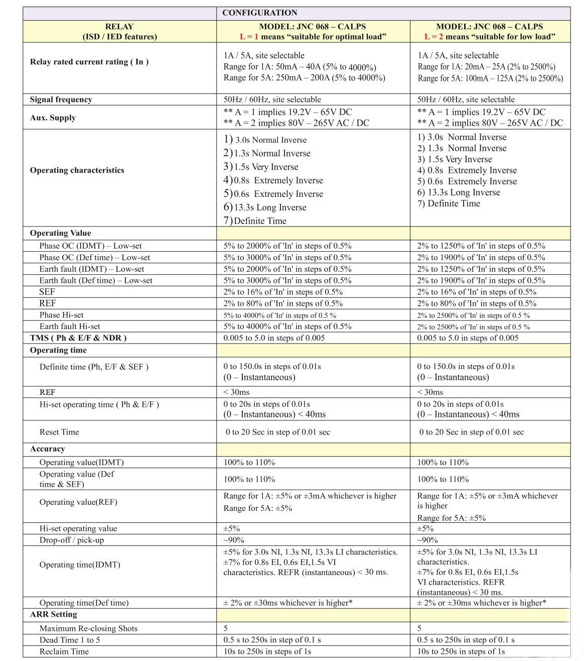
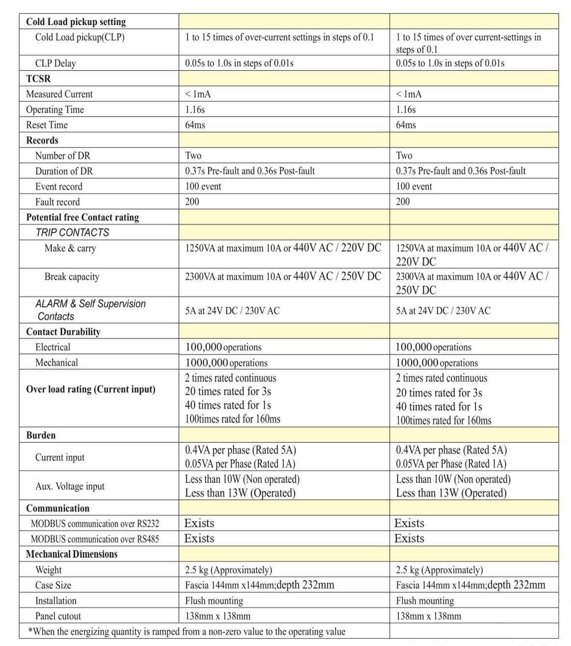
TECHNICAL DATA
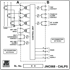
TERMINAL DIAGRAM
Ordering Information
Relay type
: JNC 068 - CALPS
Communication First Digit
: C
: 1 - Without MODBUS communication over RS 232 & RS 485
: 1 - Without MODBUS communication over RS 232 & RS 485
Auxiliary supply Second digit
: A
: 1 - 19 to 65V DC
: 2 - 80 to 265V AC/DC
: 1 - 19 to 65V DC
: 2 - 80 to 265V AC/DC
Nature of Load(on feeder) Third digit
: L
: 1 - Normal Load
: 2 - Low Load
: 1 - Normal Load
: 2 - Low Load
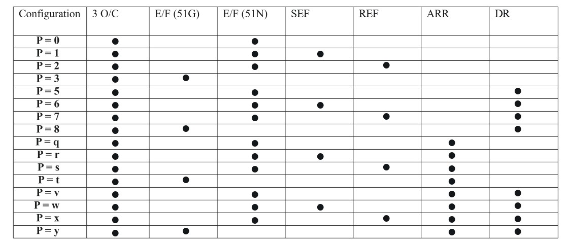
Protection Element Fourth digit
: P
Note :
51 N is derived out of the phasor sum of the 6 phase line currents whereas 51G derives its input directly from the a CT measuring the residual current through the neutral.
51 N is derived out of the phasor sum of the 6 phase line currents whereas 51G derives its input directly from the a CT measuring the residual current through the neutral.


