NUMERICAL TRANSFORMER DIFFERENTIAL RELAY
₹62,920.00
Product Code: JND 040
Time line :Products will be shipped within 3 weeks from the date of order
Stock In Stock
Viewed 11142 times
Categories
Cart
Account
Search
Recent View
All Categories
×
-
Products Category
- Earth Leakage Relays
- Electromechanical Auxiliary & High Speed Tripping Relays
- Electronic Hooters
- LED Indicating Lamps
- LED Semaphore Indicators
- Micro Processor Based Directional / Non-directional, Non-Communicable Current Relays
- MICRO PROCESSOR BASED INSTANTANEOUS / DEFINITE TIME AC VOLTAGE RELAYS
- Micro Processor Based Multi Shot, Auto Reclose Relays
- Micro Processor Based Neutral Earth Resistor Monitoring Relays
- Micro Processor Based PT Fuse Failure Relays
- MICRO PROCESSOR BASED RESTRICTED E/F RELAYS
- Micro Processor Based Trip Circuit Supervision Relays
- Numerical Check Synchronizing Relays
- Numerical Directional / Non-directional, Non-Communicable Current Relays
- Numerical Non-directional Inverse Time Current Relays Without Communication
- NUMERICAL OVERFLUX RELAYS
- Numerical Transformer Differential Relays
- Panel Accessories
- Push Buttons
- Semaphore Indicators
- Terminal Blocks & Plugs for Testing
- Time Delay Relays
- Two Stage Frequency Relays
- Micro Processor Based Inverse Time Non- Directional, Non-communicable Current Relays
- Non-directional Inverse Time Current Relays With/without Communication
- Micro Processor Based Inverse Time Non-directional, Non-communicable Current Relays
- Micro Processor Based Instantaneous / Definite Time Ac Voltage Relays
- Micro Processor Based Instantaneous / Definite Time Battery E/F Relays
- Micro Processor Based Instantaneous / Definite Time Current Relays
- Micro Processor Based Instantaneous / Definite Time Dc Voltage Relays
Shopping Cart
×
Your shopping cart is empty!
Search
×
Recent View Products
×
Product Description
Features
- Biased current differential protection
- Fast differential Hi-set
- Dual slope characteristics
- Inbuilt CT Ratio correction factor
- Adjustable 2nd harmonic restraint
- Adjustable 5th harmonic blocking
- Inbuilt Vector group compensation
- Two groups of settings
- History of 5 latest faults
Application
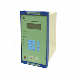
JND 040 is a two winding numerical transformer differential relay. The relay is used for protection of power transformer against hazardous internal faults.
Principle of Operation
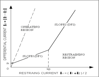
JND 040 provides differential protection for power transformer. The relay measures the line current of each phase from each of the windings of the transformer. Relay calculates the differential current (Id) and restraining current (Ir) per phase. The differential characteristics define the operating and the restraining regions. The shape of the characteristics defined by Initial pickup (ik), SLOPE1 (DF1), SLOPE2 (DF2) and break point (kp) are programmable. If ‘Ir’ is less than ‘kp’, then characteristics is defined by ‘DF1’ and is applicable for small differential currents. If ‘Ir’ is greater than or equal to ‘kp’, then characteristics is defined by ‘DF2’ and is applicable for large differential currents. If the operating point i.e. (Id, Ir) is within the operating region, then the relay trips. The relay provides programmable 2nd and 5th harmonic current restraint, which, exist when transformer is energized and over excitation condition exists respectively. The relay provides stability on external “line to line” and “line to ground” faults. The relay has in-built vector group compensation selection and CT ratio correction, hence the usage of external interposing CT can be avoided.
DIFFERENTIAL CHARACTERISTICS.

Ratings
Settings
Over Load Rating
Burden
Primary current rating :
0.577A / 1A / 2.89A / SA
Secondary current rating :
0.577A / 1A / 2.89A / SA
Aux. Supply :
20 – 60V DC
75 - 150V DC
175 – 300V DC / 185 – 250V AC
75 - 150V DC
175 – 300V DC / 185 – 250V AC
Pickup (ik) :
0.10 to 1.00pu in steps of 0.05pu
Slope1 (DF1) :
10 to 100% in steps of 5%
Slope2 (DF2) :
50 to 200% in steps of 5%
Breakpoint (kp) :
1.0 to 10.0pu in steps of 0.1pu
Differential Hiset :
2 to 20pu in steps of 1pu
CT Ratio W1 :
0.5 to 2.00pu in steps of 0.01pu
CT Ratio W2 :
10 to 50% in steps of 5%
Inrush (2f) :
10 to 50% in steps of 5%
Over excitation(5f) :
0, Dd0, Yd1 , Dy1 , Dd2, Dd4,
Vector Groups :
5, Dy5, Yy6, Dd6, Yd7, Dy7, Dd8, Dd10, Yd11 , Dy11.
current input :
2 times Rated continuous
20 times Rated for 3s
40 times Rated for 1s
20 times Rated for 3s
40 times Rated for 1s
Current input :
0.1VA per phase (Rated 5A)
0.05VA per phase (Rated 1A)
0.05VA per phase (Rated 1A)
Aux. Supply :
Less than 6W (non operated)
Less than 11W (operated)
Less than 11W (operated)
Operating Time
Accuracy
Contact Ratings
Contact Durability
Mechanical Design
Operating time :
Typical 35ms
High st operating time :
Typical 30ms
Operating value :
±5%
Operating time :
+7ms
Make & carry :
1250VA with max. current 5A or max.
Voltage 660VAC
1000W with max. current 5A or max. Voltage 250VDC
Voltage 660VAC
1000W with max. current 5A or max. Voltage 250VDC
Break :
2500 VA with max current 10A or max.
Voltage 660VAC
200 W (resistive) 100 W (inductive) with max.
current 10A or max. Voltage 250V DC
Voltage 660VAC
200 W (resistive) 100 W (inductive) with max.
current 10A or max. Voltage 250V DC
Loaded contact :
10,000 operations min.
Unloaded contact :
100,000 operations min.
Weight :
App. 5 Kgs.
Case Size :
Fascia 152 x 296 mm, Depth 250mm
Installation :
Flush mounting
Panel cutout :
146 x 264 mm
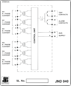
TERMINAL DIAGRAM

Ordering Information
Primary current rating :
0.577A / 1A / 2.89A / 5A
Secondary current rating :
0.577A / 1A / 2.89A / 5A
Aux. Supply :
20 – 60VDC
75 - 150V AC /DC
175 – 300V DC or 185 – 250V AC
75 - 150V AC /DC
175 – 300V DC or 185 – 250V AC


